Assignment 4: Libraries!
Demo
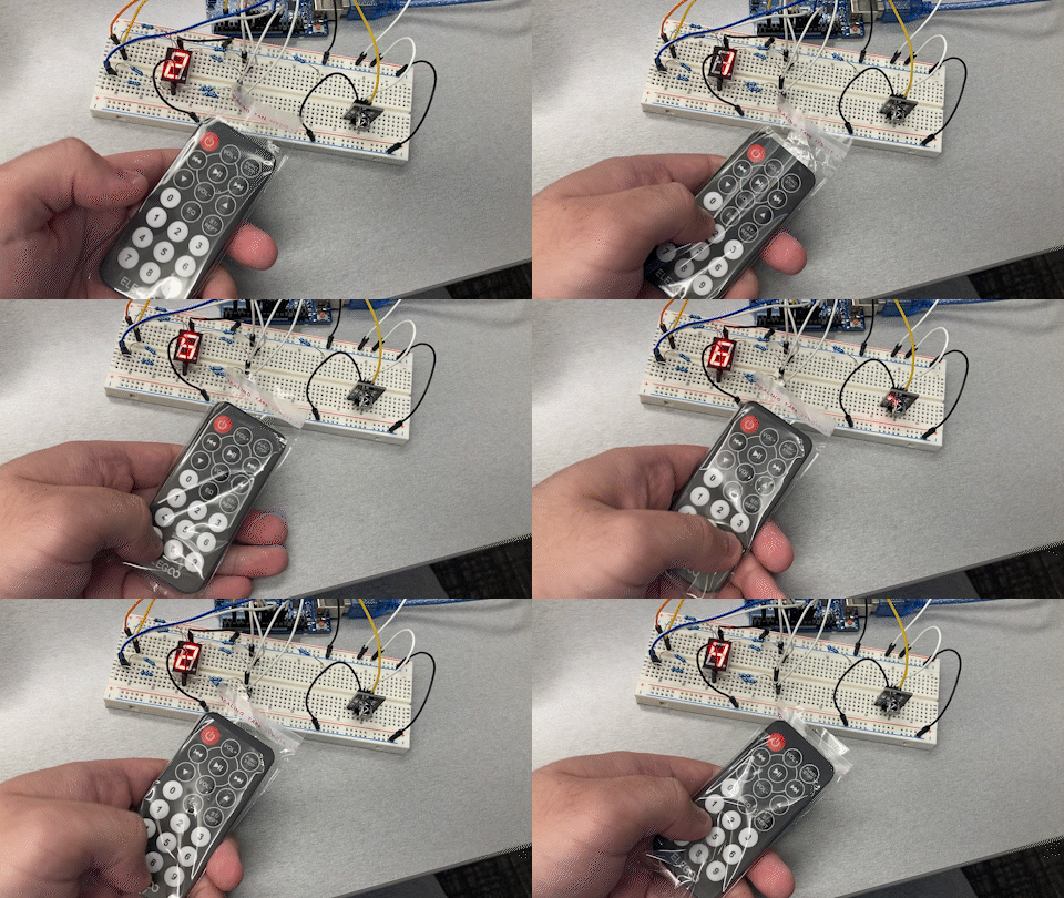
Control 8-segement display with IR remote
Demo video for 8-segment display controlled by IR remote.

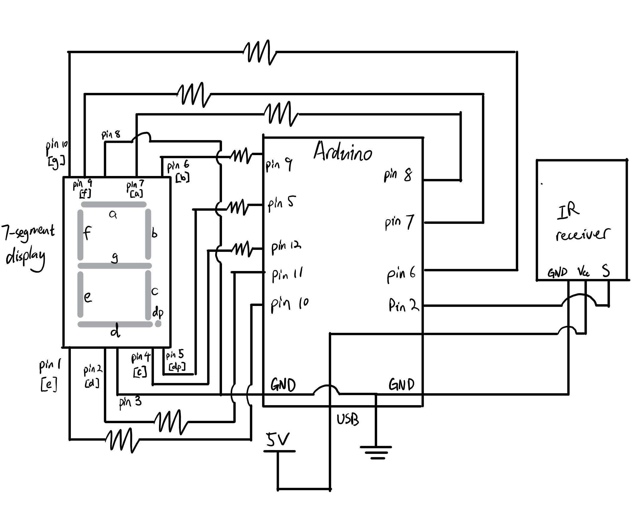
Circuit drawing
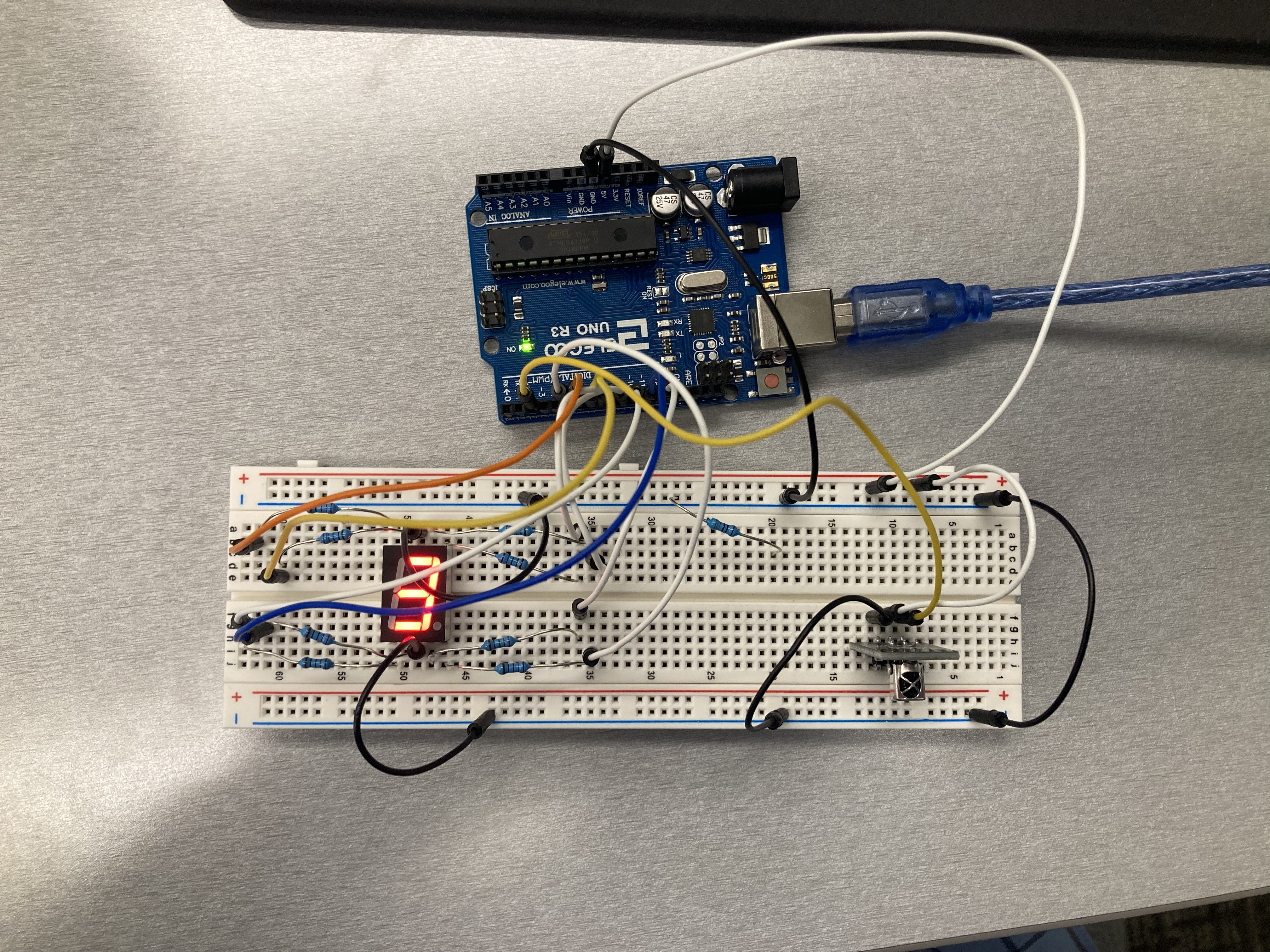
The IR receiver & 7-segment display are connected to the microcontroller’s output pins. Resistors are connected in series with the 7-segment display to limit current.

The circuit is is powered via USB connected to the Arudino microcontroller.

Calculating resistor values
7-segment display LED resistor
Because each red LED that makes up the 7 segments can operate safely within $\leq 30 \text{mA}$ of current, we need to use resisters to reduce the amount of current going through each LED.
Since we are connecting the resister & the LED in series, the amount of current through the LED is the same as that for the resister ($I_\text{L} = I_\text{r}$). This also means that the sum of voltage drop across the resister and LED should be equal to the voltage provided by the Arduino microcontroller (5V).
With these information, we calculate the minimum resistance by applying Ohm’s law on the resister. $$ \begin{align*} V_\text{r} &= I_\text{r} R_\text{r} && \text{Ohm’s law}\cr V_\text{PSU} - V_\text{L} &= I_\text{L} R_\text{r} &&\text{Substitute resister V & I}\cr 5\texttt{V} - V_\text{L} &= 20\texttt{mA} \cdot R_\text{r}\cr \end{align*} $$
A 220 Ω resister is used for the red LEDs because these LEDs have a voltage drop of 1.7V. Their resisters’ resistance to be at least $$ \begin{align*} V&=IR\cr 5\;\texttt{V} - 1.7\;\texttt{V} &=20\;\texttt{mA} \cdot \textrm{R}\cr \frac{3.3\;\texttt{V}}{0.02\;\texttt{A}} &= \textrm{R}\cr \textrm{R} &= 165 \;\Omega \end{align*} $$
Using a resistor with higher resistance than what is required here will not have an adverse effect on the longevity of the LED, it will simply cause it to appear a bit dimmer.
Arduino code
// Include external libraries
#include <Arduino.h>
#include <IRremote.hpp>   // IR receiver library
#include <SevenSegmentDisplay.h>  // 7-segment display library

// Preprocessor macros for input and output pin etc.
#define IR_RECEIVE_PIN 2  // IR receiver pin
#define DECODE_NEC        // Use NEC decode for IR signal

// Define LED pins for each LED in 7-segment display
#define PIN_DP 5
#define PIN_C 12
#define PIN_D 11
#define PIN_E 10
#define PIN_B 9
#define PIN_A 8
#define PIN_F 7
#define PIN_G 6

// Define number of LEDs
#define NUM_LEDS 8

// Array of LED pins
uint8_t LEDs[] = { PIN_DP, PIN_C, PIN_D, PIN_E, PIN_B, PIN_A, PIN_F, PIN_G };

// Shared int pointer for loops
uint8_t* ptr;

// Variable to store decoded button value
// val == -1 if the button is not a number
uint8_t val;

// Define a seven segment display
SevenSegmentDisplay screen(PIN_A, PIN_B, PIN_C, PIN_D, PIN_E, PIN_F,PIN_G, PIN_DP, false);

// Setup code, run once
void setup() {
  // Initialize Serial communications
  Serial.begin(9600);
  // Initialize all LED pins to output mode
  for (ptr = LEDs; ptr < LEDs + NUM_LEDS; ++ptr) {
    pinMode(*ptr, OUTPUT);  // Set a single pin to output mode
  }
  // Start the receiver and if not 3 parameter specified, take LED_BUILTIN pin from the internal boards definition as default feedback LED
  IrReceiver.begin(IR_RECEIVE_PIN, ENABLE_LED_FEEDBACK);
  // Print ready prompt to terminal
  Serial.print(F("Ready to receive IR signals of protocols: "));
  printActiveIRProtocols(&Serial);    // Print active IR protocol used
}


// Interactive code, infinite loop
void loop() {
  // Check for received data & attempt to decode
  if (IrReceiver.decode()) {
    // Process if the received
    if(IrReceiver.decodedIRData.protocol == NEC){
      // Attempt to match the received command into a number button
      // If a received command can be mapped to a number on the remote,
      // set val to that number
      switch(IrReceiver.decodedIRData.command){
        case 0x16:  // Case for button 0
          val = 0;
          break;
        case 0xC:   // Case for button 1
          val = 1;
          break;
        case 0x18:  // .....
          val = 2;
          break;
        case 0x5E:
          val = 3;
          break;
        case 0x8:
          val = 4;
          break;
        case 0x1C:
          val = 5;
          break;
        case 0x5A:
          val = 6;
          break;
        case 0x42:
          val = 7;
          break;
        case 0x52:
          val = 8;
          break;
        case 0x4A:  // Case for button 9
          val = 9;
          break;
        default:  // Default case: handles other buttons
          val = -1;
      }
      // Only update the seven segement display if button was a number
      if (val >= 0){
        // Update the 7 segment display
        screen.displayCharacter(val + '0');
        // Print raw IR data to terminal
        Serial.println(IrReceiver.decodedIRData.decodedRawData);
      }
    }
    // Resume IR data receive
    IrReceiver.resume(); // Enable receiving of the next value
  }
  // Program loop delay
  delay(20);
}