Assignment 3: I/O (Input/Output)!
Demo
Sensor calibration
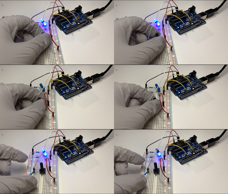
Demo video showing initial sensor calibration on startup. When both LEDs are on, capture the minimum reading from sensor. When both LEDs are off, capture the maximum reading from sensor. Both LEDs flashing together indicates calibration completion.
Adjusting brightness
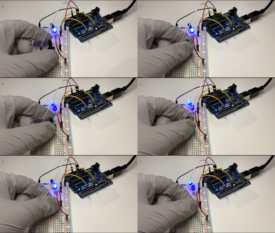
Demo showing the potentiometer controlling LED brightness in opposite directions. Turning the knob counterclockwise increases brightness for the top LED and dims the bottom LED. Turning the knob clockwise dims the top LED and increases power (brightness) for the top LED.
Serial communications
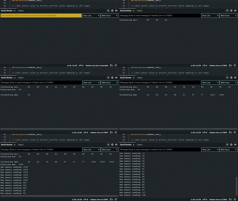
Screen capture of data being sent over a serial connection upon initial startup & regular operation.
Circuit drawing
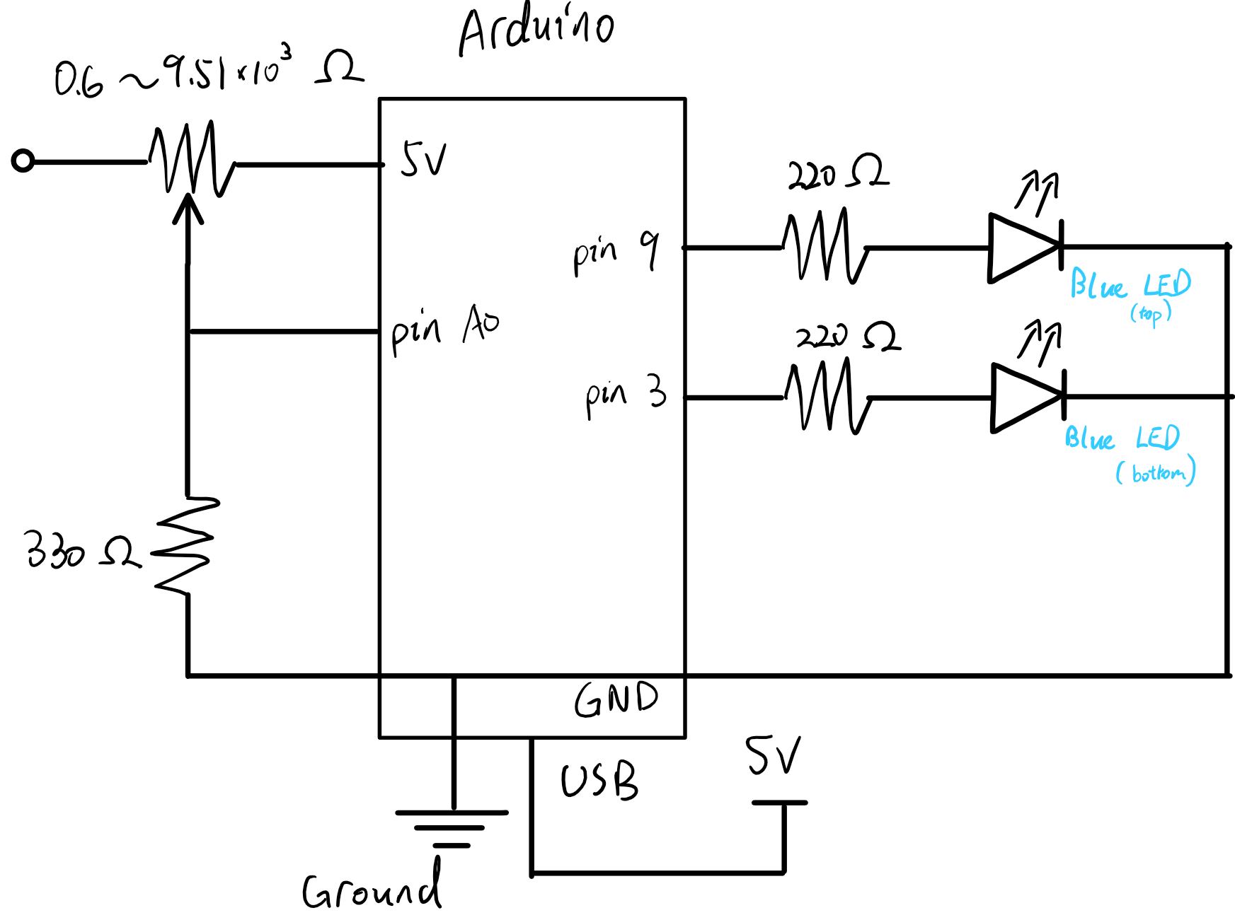
The circuit is is powered via USB connected to the Arudino microcontroller. The blue LEDs are connected to pin 3 and 9 respectively. Each LED is connected in series with a 220 Ω resistor to reduce the current through the LED.
The circuit also contains a potentiometer. It is connected to pin A0 and a 330 Ω resister (equivalent of a voltmeter) to limit current through the system.
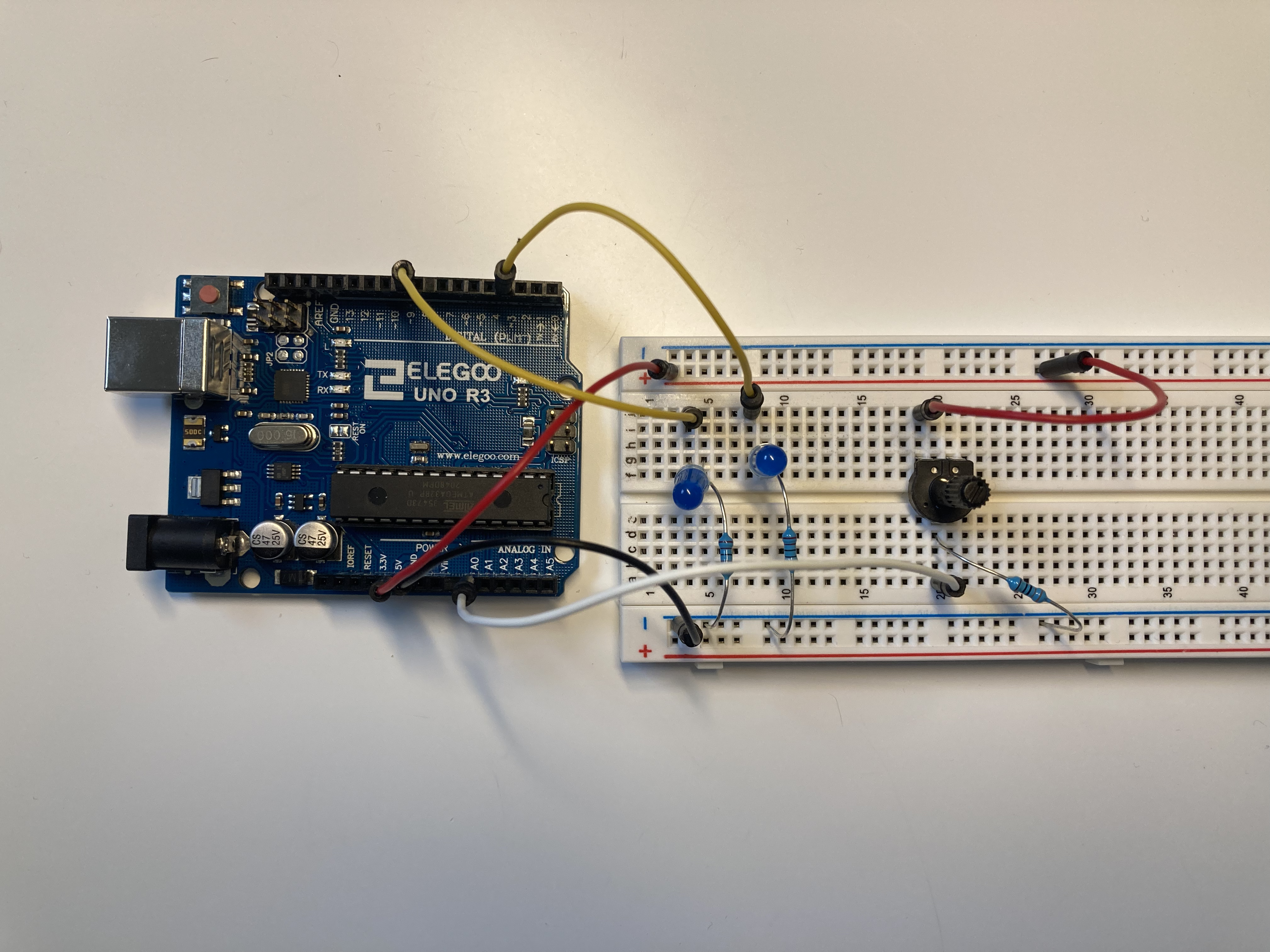
Calculating resistor values
LED resistor
Because each LED used in this assignment can operate safely with $\leq 30 \text{mA}$ of current, we need to use resisters to reduce the amount of current going through each LED.
Since we are connecting the resister & the LED in series, the amount of current through the LED is the same as that for the resister ($I_\text{L} = I_\text{r}$). This also means that the sum of voltage drop across the resister and LED should be equal to the voltage provided by the Arduino microcontroller (5V).
With these information, we calculate the minimum resistance by applying Ohm’s law on the resister. $$ \begin{align*} V_\text{r} &= I_\text{r} R_\text{r} && \text{Ohm’s law}\cr V_\text{PSU} - V_\text{L} &= I_\text{L} R_\text{r} &&\text{Substitute resister V & I}\cr 5\texttt{V} - V_\text{L} &= 20\texttt{mA} \cdot R_\text{r}\cr \end{align*} $$
A 220 Ω resister is used for the blue LED (voltage drop = 3.3V). It needs an resistor that is at least $$ \begin{align*} V&=IR\cr 5\;\texttt{V} - 3.3\;\texttt{V} &=20\;\texttt{mA} \cdot \textrm{R}\cr \frac{1.7\;\texttt{V}}{0.02\;\texttt{A}} &= \textrm{R}\cr \textrm{R} &= 85 \;\Omega \end{align*} $$ Using a resistor with higher resistance than what is required here (e.g. a 100 Ω resistor) will not have an adverse effect on the longevity of the LED, it will simply cause it to appear a bit dimmer.
Potentiometer resistor
Assuming the analog in port on Arudino is an ideal voltmeter (aka. infinite resistance), the resistor and the potentiometer are effectively connected in series. Because the maximum DC current through the GND pin for the microcontroller is 200 mA, we also need to calculate the minimum resistence for the previously mentioned resistor. Since the ground pin is shared between the LEDs and the potentiometer, we need to consider the worst case scenario where current through the circuit is maximized when the potentiometer’s resistance is approximately 0 Ω and both LEDs are on. We first calculate the current through the LEDs.
$$ \begin{align*} V &= IR &&\text{Ohm’s law}\cr I &= \frac{V}{R}\cr I &= \frac{5\texttt{V}-3.3\texttt{V}}{220\Omega} &&\text{Substitution}\cr I &\approx 7.8 mA &&\text{Round up for worst-case scenario} \end{align*} $$
Because each LED and the potentio meter are connected in parallel, we can then determine that
$$ \begin{align*} I_\text{max} &> I_\text{LED} \cdot 2 + I_\text{pot}\cr 200 \texttt{mA} &> 7.8 \texttt{mA} \cdot 2 + I_\text{pot}\cr I_\text{pot} &< 184.4 \texttt{mA} \end{align*} $$
In the worst case with potentiometer having 0 Ω, the minimum resistance for the other resistor is: $$ \begin{align*} V &= I R && \text{Ohm’s law}\cr 5 \texttt{V} &= 184.4 \texttt{mA} \cdot R &&\text{Substitue V & I}\cr R &= \frac{5\texttt{V}}{0.1844\texttt{A}}\cr R &\approx 28 \;\Omega \end{align*} $$
Considering that other on-board devices might be sharing the ground pin under the hood, I decided to be extra cautious and use a 330 Ω resistor.
Arduino code
// Preprocessor macros
#define LED1_PIN 3  // Bottom LED
#define LED2_PIN 9  // Top LED
#define NUM_LEDS 2  // # of LEDs

#define SENSOR_PIN A0 // Analog sensor port (potentiometer)


// Global variables
// Loop variable
uint8_t i;
// Temporarily saves sensor readings
long sensor_val;
// Stores sensor reading for reuse
long sensor_max = 0;    // Initial max sensor value
long sensor_min = 1023; // Initial min sensor value

// Array of LEDs in the system
uint8_t LEDs[NUM_LEDS] = {LED1_PIN, LED2_PIN};


// Helper functions
// Synchronize all LEDs to either ON or OFF state
void sync_led(uint8_t* L, uint8_t num, bool state);


// Setup code, run once
void setup() {
  // Set all used pins to output mode
  pinMode(LED1_PIN, OUTPUT);  // Set top LED to output mode
  pinMode(LED2_PIN, OUTPUT);  // Set bottom LED to output mode
  Serial.begin(9600);         // Set up serial connection

  // Calibrate min input
  // Light up all LEDs to indicate the system is measuring min input
  sync_led(LEDs, NUM_LEDS, HIGH);
  // Print text to terminal
  Serial.print("Calibrating min:\t");

  // Take 10 measurements
  for (i = 0; i < 10; ++i){
    sensor_val = analogRead(SENSOR_PIN);  // Save reading to temp variable
    // Update minimum if the measured value is less than the known minimum
    if(sensor_val < sensor_min)
      sensor_min = sensor_val;

    Serial.print(sensor_min); // Print the obtained value
    Serial.print('\t');       // insert tab character for spacing
    // Delay to allow the user some time to generate the min sensor reading
    delay(300);
  }
  // Print out the finalized min sensor reading
  Serial.print("\nFinalized min:\t");
  Serial.println(sensor_min);

  // Calibrate max input
  // Turn all LEDs off to indicate the system is measuring max input
  sync_led(LEDs, NUM_LEDS, LOW);
  // Print text to terminal
  Serial.print("\nCalibrating max:\t");

  // Take 10 measurements
  for (i = 0; i < 10; ++i){
    sensor_val = analogRead(SENSOR_PIN);    // Save reading to temp variable
    // Update maximum if the measured value is greater than the known maximum
    if(sensor_val > sensor_max)
      sensor_max = sensor_val;  // Print the obtained value

    Serial.print(sensor_max);   // insert tab character for spacing
    Serial.print('\t');         // insert tab character for spacing
    // Delay to allow the user some time to generate the min sensor reading
    delay(300);
  }
  // Print out the finalized max sensor reading
  Serial.print("\nFinalized max:\t");
  Serial.println(sensor_max);

  // Blink the LEDs for a few times to indicate end of calibration
  for(i = 1; i < 4; ++i){ // Loop
    sync_led(LEDs, NUM_LEDS, i % 2);  // Change LED state on every iteration
    delay(300); // Delay to make the blinking noticable
  }
}

// Infinite loop: Interactive code
void loop() {
  // Read from potentiometer value
  sensor_val = analogRead(SENSOR_PIN);

  // Prints raw value from the potentiometer
  Serial.print("Raw sensor reading: ");
  Serial.println(i);

  // Limit sensor value to prevent overflow (after mapping to LED range)
  sensor_val = constrain(sensor_val, sensor_min, sensor_max);

  // Map sensor reading to bottom LED
  analogWrite(LED1_PIN, map(sensor_val, sensor_min, sensor_max, 0, 255));
  // Map sensor reading to top LED (inverse)
  analogWrite(LED2_PIN, map(sensor_val, sensor_min, sensor_max, 255, 0));

  // Add some delay between reads
  delay(100);
}


// Helper function implementation
//
/**
 * Synchronize all LEDs to either ON or OFF state
 *
 * @param l Pointer to array of LEDs (output port)
 * @param num: number of LEDs in array l
 * @param state: either HIGH (1) or LOW (0)
*/
void sync_led(uint8_t* L, uint8_t num, bool state){
  // Loop through the array
  for(uint8_t* ptr = L; ptr < L + num; ++ptr){
    // Individually toggle the state of each LED
    digitalWrite(*ptr, state);
  }
}