Assignment 2: Fade!
Demo

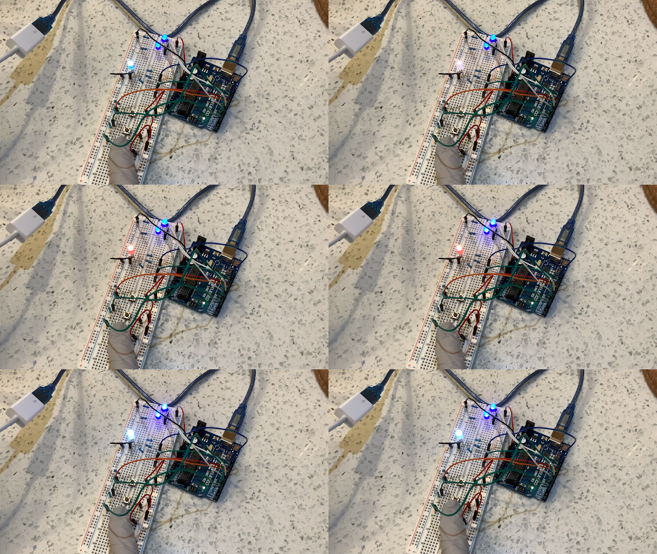
Demo showing bottom LED fading to different color on button press.

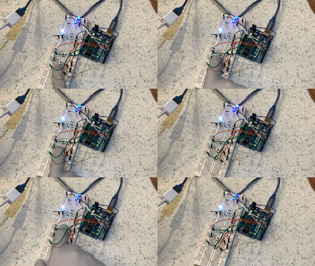
Demo showing top two LEDs’ fading duration changing based on duration of their respective button press duration.
Circuit drawing

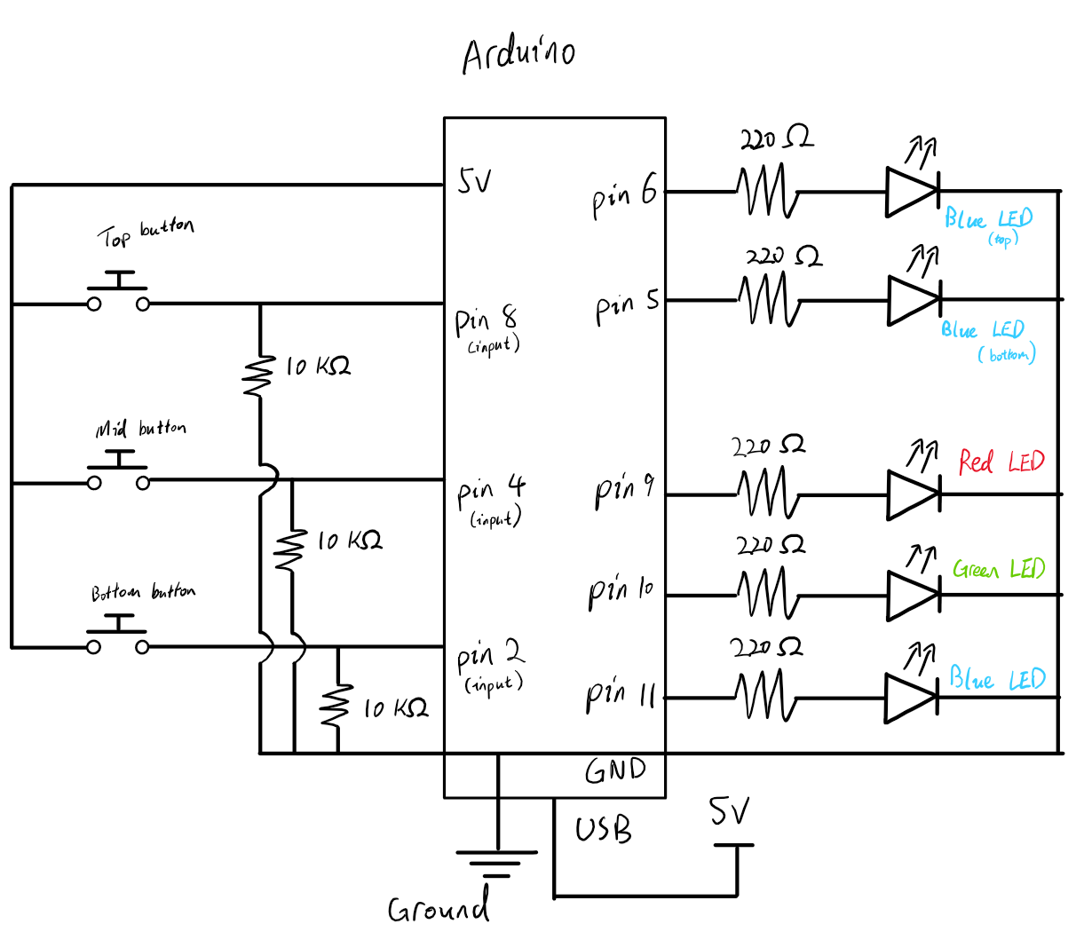
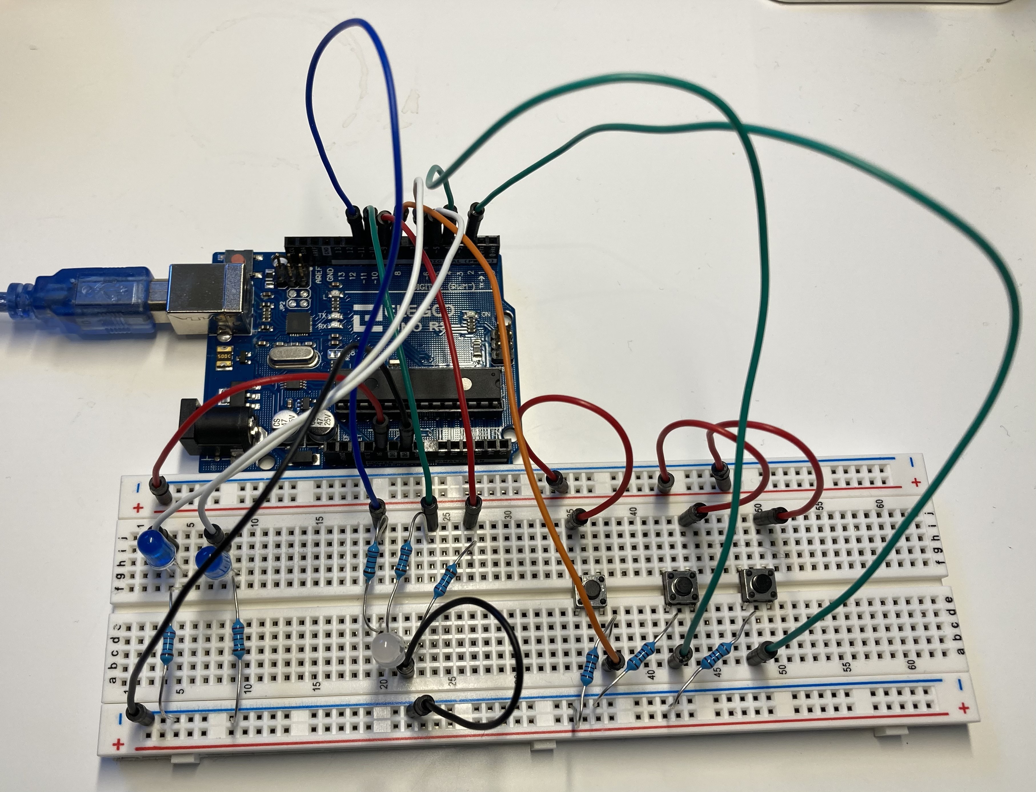
The circuit is is powered via USB connected to the Arudino microcontroller. The blue LEDs at the top are connected to pin 6 and 5 respectively. Each primary color LED that made up the RGB LED is connected to pin 9, 10, 11 for red, green, and blue. Each LED is connected in series with a resistor to reduce the current through the LED.
The circuit also contains 3 push buttons connected to pin 8, 4, and 2. A 10 kΩ resister is connected in parallel to the digital input pins to prevent a short circuit and ensure consisitency when reading from those digital pins.

Calculating resistor values
Because each LED used in this assignment can operate safely with $\leq 30 \text{mA}$ of current, we need to use resisters to reduce the amount of current going through each LED.
Since we are connecting the resister & the LED in series, the amount of current through the LED is the same as that for the resister ($I_\text{L} = I_\text{r}$). This also means that the sum of voltage drop across the resister and LED should be equal to the voltage provided by the Arduino microcontroller (5V).
With these information, we calculate the minimum resistance by applying Ohm’s law on the resister. $$ \begin{align*} V_\text{r} &= I_\text{r} R_\text{r} && \text{Ohm’s law}\cr V_\text{PSU} - V_\text{L} &= I_\text{L} R_\text{r} &&\text{Substitute resister V & I}\cr 5\texttt{V} - V_\text{L} &= 20\texttt{mA} \cdot R_\text{r}\cr \end{align*} $$
A 220 Ω resister is used for red and green LEDs because these LEDs have a voltage drop of 1.7V. Their resisters’ resistance to be at least $$ \begin{align*} V&=IR\cr 5\;\texttt{V} - 1.7\;\texttt{V} &=20\;\texttt{mA} \cdot \textrm{R}\cr \frac{3.3\;\texttt{V}}{0.02\;\texttt{A}} &= \textrm{R}\cr \textrm{R} &= 165 \;\Omega \end{align*} $$
A 220 Ω resister is used for the blue LED (voltage drop = 3.3V). It needs an resistor that is at least $$ \begin{align*} V&=IR\cr 5\;\texttt{V} - 3.3\;\texttt{V} &=20\;\texttt{mA} \cdot \textrm{R}\cr \frac{1.7\;\texttt{V}}{0.02\;\texttt{A}} &= \textrm{R}\cr \textrm{R} &= 85 \;\Omega \end{align*} $$ Using a resistor with higher resistance than what is required here (e.g. a 100 Ω resistor) will not have an adverse effect on the longevity of the LED, it will simply cause it to appear a bit dimmer.
Arduino code
// Preprocessor marcos
// Define pins for 3 buttons connected to pin 2, 4, 8
#define BTN1_PIN 8
#define BTN2_PIN 4
#define BTN3_PIN 2

// Define pins for 2 Red LEDs connected to pin 5 & 6
#define B1_PIN 6
#define B2_PIN 5

// Define RGB LED pins
#define COLOR_R_PIN 9   // Red LED    -> pin 9
#define COLOR_G_PIN 10  // Green LED  -> pin 10
#define COLOR_B_PIN 11  // Blue LED   -> pin 11

// Number of LEDs that can be controlled = 5
#define NUM_LEDS 5
// Number of buttons connected = 3
#define NUM_BTNS 3

#define ANALOG_MAX 127
#define ANALOG_MIN 0


// Global Variables
// Represents the state of a single LED
struct LED{
  uint8_t pin;    // connected pin
  uint8_t brightness; // LED power (roughly maps to brightness)
  uint8_t max_brightness; //Maximum allowed brightness
  bool increasing;// Whether the LED is increasing in power
};

// Represents the state of a single button
struct button{
  uint8_t pin;    // connected pin
  bool pressed;   // whether the button was pressed in the last program cycle
};

// Bookkeeping array of LED structs, the state of all LEDs
struct LED LEDs[] = {{B1_PIN, 0, 20, false}, {B2_PIN, 0, 20, false},
                     {COLOR_R_PIN, 10, 30, false}, {COLOR_G_PIN, 15, 30, false},
                     {COLOR_B_PIN, 10, 30, false}};   // All LEDs are initially off

// Bookkeeping array of button structs. Contains state for all buttons
struct button buttons[] = {{BTN1_PIN, false}, {BTN2_PIN, false}, {BTN3_PIN, false}};

// Pointer used to reference each LED struct (saves copying)
struct LED* led_ptr;
// Pointer used to reference each button struct (saves copying)
struct button* btn;


// Helper function
// Declare brightness control function header
void brightness_control(struct LED* l, struct button* b);


// "Main" functions
// Setup code (run once @ startup)
void setup(){
  // Loop through every button pin & set to input mode
  for(btn = buttons; btn < buttons + NUM_BTNS; ++btn)
    pinMode(btn->pin, INPUT);    // Set a single button pin to input mode

}


// Infinite loop (Interactive program goes here)
void loop(){
  // Calls brightness control helper function on blue LEDs & their matching buttons
  brightness_control(LEDs, buttons);    // Top blue LED
  brightness_control(LEDs+1, buttons+1);// Bottom blue LED

  // Test if the bottom button for controlling the RGB LED is pressed
  if(digitalRead(buttons[2].pin)){  // If button is pressed, only set button state to true
    buttons[2].pressed = true;  // Set button as pressed
  } else if(buttons[2].pressed){  // If button was just released
    buttons[2].pressed = false; // Set button state to false (only take this branch once per button click)
    for(led_ptr = LEDs+2; led_ptr < LEDs+NUM_LEDS; ++led_ptr){  // Shifts power level to all three primary color LEDs
      if(led_ptr->increasing){  // If the LED is set to increasing power
        led_ptr->brightness += random(3, 6);  // Randomly increase pwoer between 3 & 6
      } else {  // otherwise decrease power
        led_ptr->brightness -= random(3, 6);  // Randomly decrease power between 3 & 6
      }
      // Constrain power level within a set range
      led_ptr->brightness = constrain(led_ptr->brightness, ANALOG_MIN, led_ptr->max_brightness);
      // 25% chance of switching between increasing/decreasing power
      if (!random(4)){
        led_ptr->increasing = !led_ptr->increasing;
      }
    }

  }

  // Write updated brightness value to each LED
  for(led_ptr = LEDs; led_ptr < LEDs + NUM_LEDS; ++led_ptr)
    analogWrite(led_ptr->pin, led_ptr->brightness);  // Write the state of single LED from bookkeeping data structure

  delay(250);   // Waits 250 ms
}

/**
 * Control the power (~= brightness) to a given LED, optionally uses the duration of button press to
 * adjust the max brightness & period of fading LED
 *
 * @param l Pointer to LED being controlled by user
 * @param b Pointer to button used to program LED max brightness & duration of each fade cycle
*/
void brightness_control(struct LED* l, struct button* b){
  if(digitalRead(b->pin)){  //  Check if the button is currently pressed
    if(b->pressed){ // If the button was pressed in the last program cycle
      l->max_brightness++;  // Continue to increment power
      l->max_brightness = min(l->max_brightness, ANALOG_MAX); // Prevent int overflow
    } else {  // Button NOT pressed in the last cycle
      b->pressed = true;    // Update current button state
      l->brightness = l->max_brightness = 0;  // reset brightness to zero
      l->increasing = false;  // Special value to ensure the LED brightness change direction is correct
    }
  } else {  // Button is not currently pressed
    b->pressed = false; // Update button state
  }

  // Change direction of shifting brightness if we hit max/min allowed brightness for the given LED
  if \(l->brightness == l->max\_brightness \|| l->brightness == ANALOG\_MIN)
    l->increasing = !l->increasing; // Flip direction

  // Increment/decrement power (brightness) value as needed
  if (l->increasing){
    l->brightness++;  // Increasing power
  } else {
    l->brightness--;  // Decreasing power
  }
}